Sony El-7 Service Manual

• 44.5 × 105.3 × 14.0 mm (1 × 4 × in.) 13/16 9/16 Mass (incl. Batteries) 68 g (2.4 oz) Design and specifications are subject to change without notice. IC RECORDER Sony Corporation 9-877-0A0400-1 Personal Audio Company © 2003. 01 Published by Sony Engineering Corporation.

• ICD-B7 Notes on Chip Component Replacement TABLE OF CONTENTS • Never reuse a disconnected chip component. • Notice that the minus side of a tantalum capacitor may be dam- 1. GENERAL aged by heat.
Acet Actuaries Study Material. Index to Parts and Controls.. • ICD-B7 SECTION 1 GENERAL This section is extracted from instruction manual.
Hp Installer Uninstaller Has Stopped Working Windows 7 there. Electronics service manual exchange: schematics,datasheets,diagrams,repairs,schema,service manuals,eeprom bins,pcb as well as service mode entry, make to model and.
• ICD-B7 SECTION 2 DISASSEMBLY Note: This set can be disassemble according to the following sequence. UPPER LID ASSY (Page 4) 2-2. F-SW BOARD, P-SW BOARD (Page 5) 2-3. MAIN BOARD (Page 5) Note: Follow the disassembly procedure in the numerical order given.
• ICD-B7 2-2. F-SW BOARD, P-SW BOARD 6 P-SW board 5 F-SW board 4 Removal the five solders. 1 Removal the solder.
Case assy 2 CN701 2-3. MAIN BOARD 3 B 1.7x4 2 speaker (SP101) 1 Removal the two solders. 6 MAIN board. • ICD-B7 SECTION 3 DIAGRAMS 3-1. IC PIN DESCRIPTION • IC703 µPD780308GC-A58-8EU (SYSTEM CONTROL) Pin No.
Pin Name Pin Description 1 to 3 KEY1 to 3 Key input XHOLD Hold switch input AMPPOW Power down control output for power amplifier IC (IC103). • ICD-B7 Pin No.
Pin Name Pin Description WAKEUP WAKE UP signal input RTCINT Real time clock (2 Hz) signal input FLMPOW Flash memory power ON/OFF output DSPIFACK I/F acknowledge signal input for DSP IC (IC101). LMUTE Line mute ON/OFF signal output.
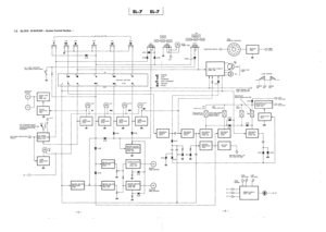
• ICD-B7 MEMO. • ICD-B7 3-2. BLOCK DIAGRAM A/D,D/A CONVERTER DSP IC101 MIC101 IC103 POWER AMP SP101 47 MIP LOUT0 J101 RV101 SPEAKER 46 MIN (PLUG IN POWER) VCCA +3.3V (VCC A) Q101 BYPASS MUTE +3.3V (VCC B) 25 27 58 24 54 X101 4.02MHz. • ICD-B7 3-3. SCHEMATIC DIAGRAM — MAIN SECTION — • Refer to page 14 for Common Note on Schematic Diagrams, Waveforms and IC Block Diagrams. IC B/D C127 IC103 TP104 SP101 TP105 TP501 TP503 C128 C123 R120 TP107 R125 C125 AGP100.